Hardware serial pins on Pi
|
|
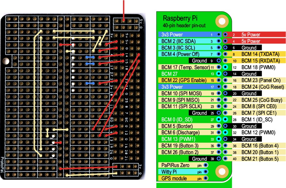
The UART TXDATA and RXDATA pins (8 and 10) are already physically connected on an add-on board (PaPiRus Zero). Whilst this can be worked around by not enabling the PaPiRus board (which kills serial) until about to shut down, I want to know whether I can specify two different pins, such as BCM 5 (pin 29) and BCM 6 (pin 31), to be used for the UART TX and RX DATA right from initial start up. The Serial module would then expect to use those pins and not be affected by the PaPiRus board. I can build a new ROM if I can find where to say ‘use BCM 5/6 rather than BCM 14/15 for the serial port’. Presume this is somewhere in the HAL. Alternatively I need to be able to resurrect BCM 14/15 from general GPIO use, back to UART use so that the Serial module will listen to serial data again. Haven’t managed that yet, hence the para above. Any help/comments please? |
|
|
I’d recommend using the diagrams on elinux.org for working out what functions can be mapped where (and on which boards). http://elinux.org/RPi_Low-level_peripherals The Pi has two serial ports, a PL011-compatible serial port and the “mini UART”. Currently RISC OS only supports the PL011, which is referred to as UART 0 on elinux.org. If you check the chart then you’ll see that TXD0 can be routed to GPIOs 14, 32 or 36, and RXD0 can be routed to GPIOs 15, 33 or 37. But GPIOs 32/33 and 36/37 are only available on the compute module, so you’re out of luck with remapping the serial port on a standard Pi (and it doesn’t look like the mini UART will help you either). |
|
|
so you’re out of luck with remapping the serial port on a standard Pi Many thanks. It will have to be plan B then. Fortunately the only situation where I use the PaPiRus display (which is hard-wired to use pins 8 and 10 on the header) is where I have a breakout board between the display and the rest of the stuff. If I use pins BCM 5 and BCM 6 instead I can solve the issue in hardware (provided I can cut the tracks between pins 8 and pins 10 on the two headers). Underneath (on the LH 40 pins) is a female header with extended pins which I bend over to connect a few of them to the pads. On top on the RH 40 pins is a male header onto which the PaPiRus display attaches. The white dots are where an OLED display and a GPS module are mounted.
|

